


Jan Dietz
-
Joined
-
Last visited
Posts posted by Jan Dietz
-
-
You will still need a way to load the power supply with 2 amps somehow. If you have a way to do that (lights, phone, random stuff) you can measure the amperage with the multimeter in series, and if you're happy you're drawing 2A, measure the voltage under load and see if it still is within specs.
(+) -- (Multimeter in Amp range) -- (Load)--- (-)
-
 1
1
-
-
Volt meter, Amp meter and 2A load (10W resistor or a few lights), measure Amps and at 2A voltage drop should be within nominal.
This will get you into the ballpark:
https://th.rs-online.com/web/p/panel-mount-fixed-resistors/1073302
Little cheap meter you can leave in circuit:
-
-
 1
1
-
-
-
Nice project!
Only think I'd consider, when using something as powerful as an ESP-8266, is to get rid of the additional controller.
You would need a level shifter and maybe some more I/O ports.. and these are available all on nice chip:
https://www.nxp.com/docs/en/data-sheet/PCA6408A.pdf
-
2
-
-
- Popular Post
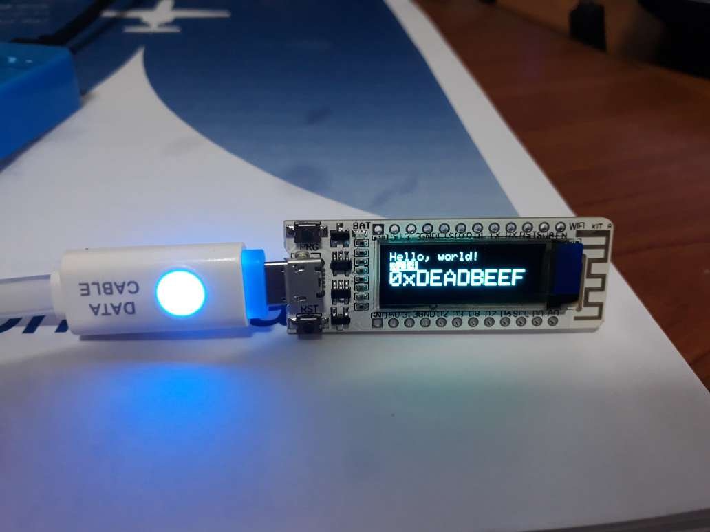
I received the tiny little boards I linked above and they work very nicely. Was a bit of a pain to track down the correct connections, but here it is:
https://github.com/Heltec-Aaron-Lee/WiFi_Kit_series/blob/master/PinoutDiagram/WIFI Kit 8.pdf
Works fine with the Adafruit library
#include <SPI.h>
#include <Wire.h>
#include <ESP8266WiFi.h>
#include <Adafruit_GFX.h>
#include <Adafruit_SSD1306.h>

#define SCREEN_WIDTH 128 // OLED display width, in pixels
#define SCREEN_HEIGHT 32 // OLED display height, in pixels
#define OLED_RESET    16 // Reset pin # (or -1 if sharing Arduino reset pin)

// Declaration for an SSD1306 display connected to I2C (SDA, SCL pins)
Adafruit_SSD1306 display(SCREEN_WIDTH, SCREEN_HEIGHT, &Wire, OLED_RESET);

void setup() {
  display.begin(SSD1306_SWITCHCAPVCC, 0x3C);  // 0x3C is address of the display
  display.display;
}
-
3
-
- Popular Post
Just FYI and to whoever is interested in this stuff, I just ordered a handful of these thingies to play with:

https://www.lazada.co.th/products/i1510560958-s3992606381.html?urlFlag=true&mp=1?
The price is right and saves making patch boards.

-
3
-
-
-
Could be an overload on start up, maybe disk drives or fans getting sticky when cold.
Second time 'round they'd have spun a bit and will drain less power.
-
1
-
-
From Google Support:
The issue with Gmail has been resolved for all affected users as of Thursday, 2020-08-20 04:12 US/Pacific.
We will publish an analysis of this incident once we have completed our internal investigation.Maybe related:
-
1
-
-
-
- Popular Post
I would keep the LEDs but go for a capacitative (reactance) voltage dropper, as per the APP note.
-
2
-
 1
1
-
- Popular Post
Ah yes, direct power from mains, a great way to electrocute yourself AND your friends ????
Pure resistive works but as you might have noticed it's a much better heater than a light source.
If you do insist on living on the edge, here is a great app note from Microchip regarding resistive and capacitative power circuits, including the formulas to calculate your components:
-
2
-
1
-
1 hour ago, mtls2005 said:
No clue why they're even attempting this as it will only
- generate more interest,
- appeal,
- book sales,
- appearances, and
- expose DJT's indecent behavior towards his family to more people.
There you go, 5 excellent reasons you give yourself right there.
More profit for the family.
-
BTW 6.3V is not critical, it's just where it will have the longest life / correct heating.
But as tubes are quite resilient you can get away with probably anything between 5 and 8 volts or so.
-
1
-
-
This one might suit you even better, a little smaller, and more of your requested voltages:
Input voltage:AC220V(red, red)
Output high voltage:AC230V-0-230V 40MA
Two groups of output filament voltage
①Single group AC6.3v 1a:
② Single group AC13V 0.6A
-
2
-
-
Something like this should be a good start.
No need to rectify the 6.3V, AC will be fine for the heater
-
2
-
-
If it is a '2TB' USB stick for 1,000 THB I can guarantee you it is fake.
Probably has a few hundred MB and a hacked controller chip.
Would explain not able to write more than a certain amount of data before the trouble starts, as the memory isn't actually there.
There are tools available to check the real capacity, but my recommendation would be to chuck it.
-
2
-
-
It'll work fine, the charge and power circuits in the laptop itself are designed to work with ripple from the standard cheap AC brick.
Internally the main voltage will be 'mainly' used to top up the battery, so there it totally doesn't matter
It will then go through a bunch of DC/DC converters to reach the internal working voltages of 5V, 3.3V and 1.8V or less for the CPU/GPU.
so plenty of headroom for a bit of ripple.
-
Reformat your USB stick to NTFS filesystem.
https://www.windowscentral.com/how-format-usb-flash-drive-windows-10
-
With RichCor on this, a decent cable checker can tell you to the centimetre how far away the problem is (short or open)
And if it has to be replaced and is in a conduit, got with Yellowtail's suggestion, no need to open up anything, just pull a fresh one using the old one, might need a little 'persuasion'
Here are some samples of the test equipment you're looking for:
-
1
-
-
Looks like something you can find for around a hundred Baht in Home Pro, if you can dodge the zombies that roam around mumbling 'Mai Mee' long enough to find it yourself.
-
 1
1
-
-


Switching adapter current output
in The Electrical Forum
Then again 5V 2A (10W) is about nothing, and any switcher made in the last 10 years should easily do that without letting out its magic smoke.