
Crossy
Global Moderator
-
Joined
-
Last visited
Everything posted by Crossy
-
Or
-
Golden Earwig - Radar Love. L
-
Better, or worse??
-
It's certainly worth getting a guesstimate to move the place, but I suspect it would be cheaper to just build a new one. https://www.sanantoniouncovered.com/2014/01/san-antonio-sets-world-record-largest.html
-
It really needs to be toughened/tempered for safety. https://www.agc-flatglass.co.th/ should be able to create you a suitable and safe table top. Note, it has to be cut to size before being tempered.
-
I used to date a girl named Beverley ???? Just watch one taking off. "Trundle, trundle, drone, drone, trundle ..."
-
Let's pop this over to Visas for a wider audience.
-
Having to actually pay doesn't seem to have discouraged many passengers. 4bec2aa5-86b9-42d6-86d0-17083a0d985c.mp4
-
I never really liked the English Electric Canberra (the Lightning was a different beast altogether): - But you really wouldn't want to be on the receiving end of this bad-boy, Handley Page, Victor! OK, I just needed an excuse to post images of some amazing British aircraft! Bonus image. Blackburn Buccaneer.


-
One of my attempts got "buffalo", at least it has an "f" and could be found on Thai farms. It also got "female goat", "ferret" and "horsefly".Only if you have a Time-of-Use meter, which most of us don't.As an addendum to my earlier post, you will likely end up having to provide poles and wiring from the meter position (wherever PEA provide it) to your home. PEA often have crews who moonlight, have the specialist kit, and are much cheaper than a private contractor. Our poles were installed on a Sunday, by a crew in PEA uniforms and driving a PEA crane truck, the poles are stamped "PEA". Pay the supervisor, cash of course.Provincial Electricity Authority - the people who you need to talk to about getting a supply. Find your local office and go along with a Thai speaker and a Google map of your place which includes the nearest power. They will tell you what they can do for you. Don't forget you will also need water which may or may not be available as a mains supply. Time for a bore ???? EDIT See this thread too: -Yes, a different rate for "construction" supplies, about double the regular rate. For a permanent supply you need to pass an "inspection", by the authority. IIRC the meter "type" on your bill should tell you what rate you are on. Alternatively, from your total cost and consumption in kWh you should be able to calculate a rough per-unit rate. If it's over about 6Baht per unit you are likely on a construction supply.Are you still on a construction supply? That's going to be double the rate per kWh of a permanent supply.Certainly, Thailand has no such blanket requirement, but it depends upon the type of wire/cable in use. Single insulated wires need to have secondary protection (conduit), insulated and sheathed cables don't, although they are often run in conduit for concealment over at least part of the run.And I now need to get tea out of my keyboard!Flame removed and thread closed.Yup, a real product. At 2% (it's not really going to contain less) salt it would go well with chips!
 Well, no visit from the blue-meanies yet, but we're staying on no-export for now. Our numbers for June (export was disabled on the 18th).
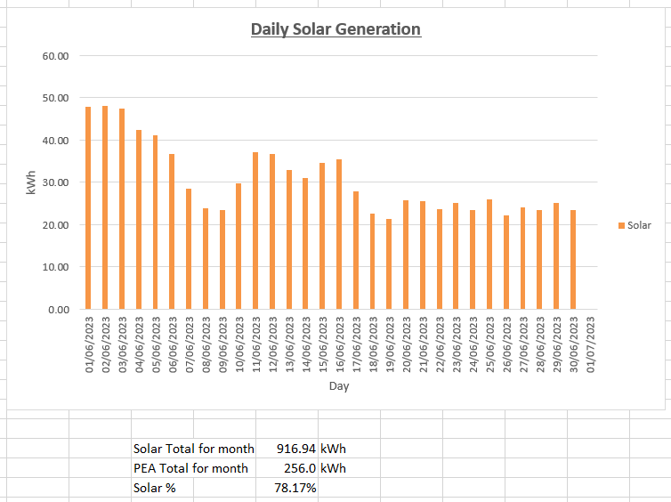 At 311 for 6 we could be in trouble ???? 324 for 8 at 18.25 Thailand 325 for 9 at 18.27 And now 325 all out - 91 runs behind.Make them hail-proof and nature will develop better hail Baseball-sized hail took out a 5.2-megawatt solar farm in Scottsbluff, Nebraska, on Friday, as part of a giant supercell thunderhead that moved across eastern Wyoming and into Nebraska. https://cowboystatedaily.com/2023/06/27/baseball-sized-hail-smashing-into-panels-at-150-mph-destroys-scottsbluff-solar-farm/This ^^^ waterlogged pressure tank.