

Polarizing
-
Posts
158 -
Joined
-
Last visited
Content Type
Events
Forums
Downloads
Quizzes
Gallery
Blogs
Posts posted by Polarizing
-
-

A small update, also to check if I did everything correct.
I bought the authentic wago's to support their business!
hmm the small pipe between junction box and backbox is loose,shall I just remove it and let the wires loose there or is it okay as it is?
currently waiting for a smart dimmer and the backbox for it.
By the way I had problems with opening up the holes on the junction box, i tried to slam it with a flat screwdriver and hammer but it didn't break open, so I just cut it open and its not neat at all. I also dont have the pvc pipe connectors for it. I think those are just minor and can be neglected. Please correct me if anything is wrong! Thanks
-
18 hours ago, Metropolitian said:
You want them there?
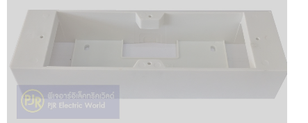
Consider taking out or modify that square and put in a long wall mount box.
I have bought mine on Shopee at 'pjrelectric' ,The box : click here
The plate: click here
This post really inspire me, the amount of detail u put in someone else's work without reward is insane. Are you around onnut, Ill buy you dinner hahah!
Also thanks so much for sharing that junction box and link. Whats your background? Your drawings are so clear and detailed! how did you get to where you are now and is this just a hobby for you (helping out electric rookies ;D, saving peoples life etc)?
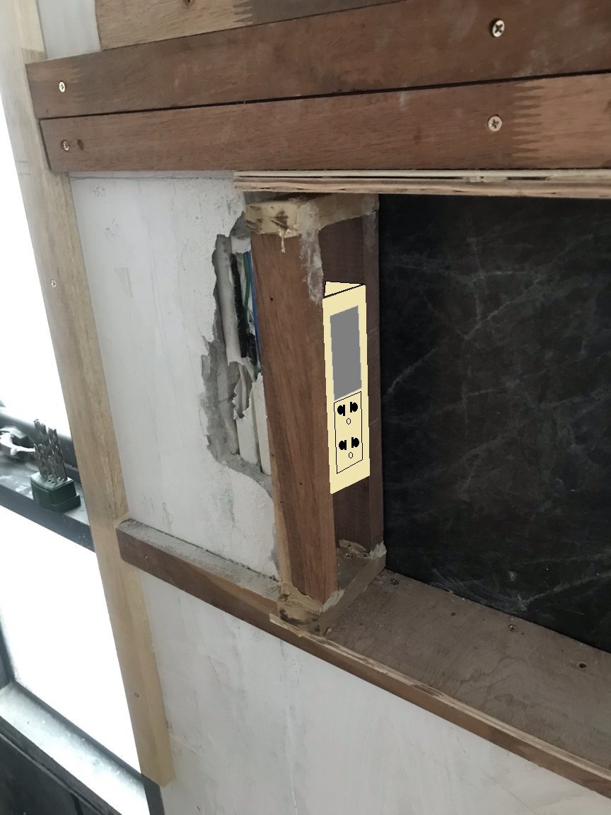
@DrTuner Thanks for your opinion, I was planning to do a smart switch at the top and there 5cm under the sockets. I want to maximize the space so no table within hand reach, as minimal as possible. We tend to still charge our phones with cables, otherwise I might consider digging a bit of wall and put a wireless charger underneath the horizontal part in the alcove and eliminating the sockets... just a future thought tho, since I dont really chase mobile phones... still on iphone 7 here hahaha
-
 1
1
-
-
4 minutes ago, ding said:
As an electrical inspector, I'm speechless. I sincerely would not know where to begin in trying to be of help.
In the USA, every splice must happen in a listed box and every box must be accessible with a cover.
But I know... TIT.
Mind to share some knowledge? So a listed box is a junction box right?
What else? you are free to scatter random thoughts XD -
2 hours ago, Metropolitian said:
Or where is the 8 shaped hole in the wood beam?
Will the bed be positioned at that location? Consider keeping one of the outlets below, you can switch that outlet by adding one more switch with the other two (you can have 3 in a row).
And the setup for the led strip at that outlet below or the bed.
Many led strips are powered by a adapter, but there do exist led strips working on 220v. Either way it is useful to have a power outlet near where you will mount the led strip.
Colored ledstrips has 4 or 5 (with warm white included) wires. DC distance over wire is best kept short.
i am working on everything as i talk and think, so the 8 hole wasnt in the picture yet and it turned out to be a wooden square where I will just mount it on a sheet of thin plywood
and I will not widen the alcove, i was so happy i was finished as it makes a lot of dust and noise, also I am not really the most prefered one by my juristic, if you want to read up on that (there's a thread about that if you are interested, called where to buy shower niche/lintel).
Actually, I want to replace the light switch with a smart switch, probably by koogeek (koogeek sucks hard, but it works and is much cheaper than lightwave RF).
it has only a two way switch. But now I think of it, it might be cool to control the led strips seperately.... hmmmmz hahah Anyways I really want it to be smart via siri, any ideas?edit: as you can see the space is really tight there, do i really need ajunction box?
-
38 minutes ago, Crossy said:
1.5 should be on no more than a 16A breaker, but there's no issue with running an outlet that's not powering your welder or the like.
For your LEDs I would provide an outlet into which you can plug the adaptor (put the outlet on a switch if you wish). Plenty of kits around that don't need soldering / wiring skills.
Beware, lighting under the bed will disturb the monster and he may come out at night and attack!!
so putting it on the same switch is not possible? I dont want to have so many switches
-
@Crossy @Metropolitian
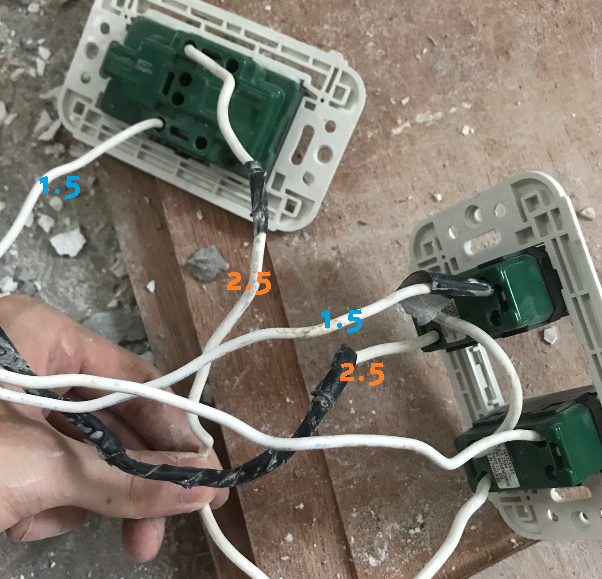
Some of the cables in the tube with white cables are indeed 1.5, very sharp of you.
What should I do with it? I guess to replace them would be too much of a hassle...
From my understanding, if a cable is thinner, there can go less amp through there?
I decided it might be a better idea to put the led adaptor not with the outlet and switch as it would be too cramped and I want to save space to leave the niche/ledge as wide as possible. So I want to install led strips under my bed and in the back of the niche, which will be connected with one of the switches.
I am not familiar with led strips wiring, how many wires and what kind should I leave in the white wire tube for this to work? This involves soldering right? As it will go from switch -> long wire to adaptor under the bed-> led strips-> wire to the niche-> led strips
Is this understandable? if not I will take more effort into drawing it out. Thankss -
4 minutes ago, Crossy said:
Nothing at all wrong with the metro-method, it should actually be wired like that now ????
If you can find a ground to hook up to you can do that too, where does that green wire in the tubes go (is it even ground)?
the collored wire tubes are going to the right circle, remember the "neutral ground reversed" thread? Yeah that outlet
-
1
-
-
6 hours ago, Crossy said:
Ignoring the no-earth and outlet polarity issues for now do the switches work as it is now?
If so mark the switch wires individually, take a photo. Disconnect the switch wires and pull them up the tubes. Re mark the wires before you shorten them. Cut and strip and put the wires back in the same holes on the switches.
How are you going to get the back box into the wall, cut it to go around the conduit?
EDIT Does one of the switches control the outlet? If so you're going to need a longer link wire, but the principle remains unchanged.
Well actually I was trying to cross some crossy rules regarding backboxes, but you detected, haha. I planned to put the switches on the left side of the niche/ledge, where I created a 8 shape out of those wood beams and just screw it on there. Having a backbox there would limit me so much since I plan to jam in a led adaptor too. Too dangerous? Let me know.
Everything works it is now. The method you mentioned is ofcourse the foolproof one, but it does not solve the no ground issue. Or, would you only steal the ground. Is there anything negative about the method metropolian and I discussed?
-
18 minutes ago, Metropolitian said:
Thanks for the detailed explanation, I will try it out soooooooon :D:D
-
8 minutes ago, Metropolitian said:
Just to be sure, there was a reason there are two tubes coming down from the ceiling.. ????
the reason was, the previous owner was not a fan of breaking into walls, so he or his sparky pulled it from somewhere and built builtin furniture around it. When I moved in, i removed the builtin furniture and jammed that tube in the wall without a detailed plan of how I am going to finish it. As time progresses, my plans became more clear haha
-
4 minutes ago, Metropolitian said:
The steps are:
1. With the switches in 'off' position ; first measure which one of the white wire is the 'hot wire' and mark it.
- If it is the one with the many black tape, then we know that that one was supposed to be the blue wire (in your case blue, in proper case it's brown or red). and also means that at the light points the fittings are neutral and switched-live.
2. pull the wiring out the new hole if you giving up the holes beneath, are you?
3. Forget the neutral in the left pipe just leave it here for future 'smart switch'
4. At the location of the hole use the wiring from the right pipe for the outlet. (Get a wall plate for both switches and power outlet.
For the right wire, to be sure about the wiring:
1. Measure between the blue and white = 220v
2. Measure between the green and blue = 220v
3. Measure between the green and white = 0v
4. Disconnect the neutral bar from the main switch (this turns off everything in home so do during the day and in the right order: mains off. disconnect. mains on)
5. Measure between the green and blue = 220v
If step 5 is true, then the wiring at the outlet is ok and green is really the earth wire.
Thanks for trying to understand my abstract artwork! this kind of answer was exactly what i was looking for!
-1 There should be at least 2 hot wires right? 1 for each of the lights? In which hole should I put it then? I never wired lighting before and do not fully understand that point.
-2. yes giving up the holes beneath
-3 Everything is on the same breaker, does this mean I can replace my old switch with a smart switch? -
15 minutes ago, Metropolitian said:
It looks like it is.. or it's an effect of angle/fisheye from the camera ????
How can I check it?
-
8 minutes ago, Metropolitian said:
Then I have to forget about the coloring in the CU. We can't rely on the wiring system, and coloring, in the CU and this situation outside.
Four white wires going to the unearthed socket and switches, one of them being neutral and one live and two switched live (or neutral..).
There must be a tap in the ceiling/wall where the blue wire became white.
Now I can't be sure that the switches are switching live OR the neutral wire.
And who can tell, that the 'wrong' socket is indeed wrong, maybe it is good but somewhere in the line the color of the wire changed.
With good testing and marking we can be sure.
Photos are getting useless now, unfortunately.
As far as I can tell, i see no thinnier wire here. All same sized. We don't know which wire exactly is.
The switch and the outlet from the upper picture comes from the left circle.
All 4 wires are pulled somewhere from the ceiling, since thais don't match colors they became all white, no surprise here.I have testing gear, but what I am more interested in a step by step plan than to actually test it, because I drilled into a wire somewhere else in my condo and I did not fix that yet (same breaker switch).
and we dont know if the wrong socket is really wrong or not for now, but I know how to confirm that.
I actually think that this picture might confuse people even more haha...
-
2 minutes ago, Metropolitian said:
I think it could be interpreted as: For future installation of a smart switch, there need to be a neutral wire present.
Most switches only has the live wire. One hot live wire coming from the CU and one switched live wire going to the lightpoint. At the light point there is neutral.
Okay what im saying is that I have at least two neutrals there. One in the tube with collored wires, one in the white wire tube.
-
3 minutes ago, bankruatsteve said:
No idea what you want to achieve. You mention no ground and wanting to do something instead? NO. Ground is ground. There is no such thing as an "extra neutral". There is no such thing as a "smart switch" using such.
What is it that you want to do? "Moving the outlets and switches to the tubes" is not enough information.
if you click on the link I provided you can see that in the socket there is no ground connected, the picture that steven posted does not show the whole picture. How do we solve that. Well in the picture with the two tubes where I made the two openings, you can see that theres a tube with colored wires in it. We can just use those three wires to make the outlet.
So when we disconnect the outlet from the white wires, there are some wires that are left over (If its a neutral, I would think that I can use it for a smart switch)
I just want to move the outlet and the switch to where I made the tube openings... -
Hi TV again!
https://imgur.com/gallery/BpfBrHb
I want to move the outlet and the two switches to the tubes where I created the hole. The left tube with 4 white wires is leading to the outlet and the switches CURRENTLY, however since there is no ground wire in the socket I am thinking of connecting the right tube's collored wires with the socket (this one is leading to the socket that was wrongly wired that I posted yesterday).
The challenge for me would be to determine how to wire the switch, can someone guide me with this? And since I will be using the colored wires, does this mean I have an extra neutral which I can use for a smart switch if i wish to do so?
-All of these wires are on the same switch in the breakerbox.
Thanks!! -
14 hours ago, lopburi3 said:
These copies (Wago is brand name) are very reasonable price now (a newer version is available) and make a much better connection and are just about foolproof.
Do you know what these 3 conductors (3 holes) are used for? Do I need them and if so, I want to read more about them. Where can I do so?
Or do I only need the the two holed version? -
10 hours ago, Metropolitian said:
First I have checked your CU, a split unit that is.
The wiring is very neat, only the coloring... well.. not according the standard but we will leave it at that.
The installers even used a nice coloring ring at the mains input. In your location Blue is hot and high as the sky and White is the neutral, Green is the right one and is Earth.
One thing about the wiring in your CU, I do see -one- brown wire, it is used in your case as neutral wire, do you know where it goes? Has it a right 'marking' at the end point? (white tape or marking 'N' )
Now your outlet. If the green wire is connected to the N and white is connected to the earth symbol. Then yes, according to the setup in your CU, this outlet is wrongly, not badly, connected. I can wildly assume that this socket is on the 'unprotected' side of the CU. If this socket was on the RCBO protected side, then it would trip as there would then be imbalance between the L and N at the RCBO.
Have you checked other outlets and their wiring?
Thanks for the summary, I have no idea about the brown wire, wild guess would be a newly installed neutral from a smart switch, but I don't think so actually since the installer of that neutral doesn't look like he had a brown wire. Does it matter much?
I need to check other outlets and their wiring ofcourse, but can only do so after I know how to do this one. Most outlets are connected with white wire so I will get it checked by removing the neutral from the busbar and test the voltage from the outlets. -
2 hours ago, jojothai said:
Note: i have seen wiring in distribution boards that has some localised connections by winding wires together and tape. If you see any around the board like that i would change them for a proper plastic connector.
you mean wire nuts right. Yes, every connection in my home is done the tape way and im about to replace it all, but I don't know the size to buy for wirenuts haha
-
Quote
Even being careful i still realised how dangerous it is going into the board. You have to be very disciplined and methodical.
@jojothai I mean what did you realise specificly when u went into the board? I mean if I am going to turn off the main power and touch everything with a neon first, I should be okay right?
-
9 minutes ago, jojothai said:
My wiring is fairly complex. The electrician managed to do it very well. He still got one part reversed.
I did similar to what bankruat steve says to check and then corrected the mistake.
Even being careful i still realised how dangerous it is going into the board. You have to be very disciplined and methodical.
I also noted a few other things that needed improving. When you do get the check done. I suggest check all the connections are good. Some of mine were loose.
What were the specific challenges u faced?
-
1 minute ago, Crossy said:
OK a split supply CU, right hand side is RCD protected, left is not. Two neutral bars with white wires. Ground bar with all the greens on the left.
Is the outlet in question on the left or right set of MCBs?
Are all the outlets wired like that?
outlet in question is on the left side, its number two, if im not mistaken.
I don't know if all my outlets are wired like that since they connect it to white wires, some connections are hidden behind builtin furniture. because you know.. haha tit. -
- Popular Post
- Popular Post
1 minute ago, jojothai said:Yes it requires additional testing.
Do not attempt to do anything in the board unless you are well experienced with such things and know the dangers.
If not, get an electrician to check it.
the problem with getting an electrician here is that they really don't care, as long as it works. (that is my experience)
-
2
-
 1
1
-
By the way I bought a very cheap, around 130 thb multimeter at tesco lotus before, which I regretted (because i thought it might not be safe) and never used. You think its safe to use or just throw it away hahaha


schematic.jpg.15621b901f9bb59b9b7bc6a69beb6fa4.jpg)


How to wire this?
in The Electrical Forum
Posted
Do I need a 3 holed wago in order to control 2 ledstrips at different locations ????