.png.3b3332cc2256ad0edbc2fe9404feeef0.png)


Metropolitian
-
Posts
1,239 -
Joined
-
Last visited
Content Type
Profiles
Forums
Downloads
Posts posted by Metropolitian
-
-
1 hour ago, bankruatsteve said:
There is no such thing as an "extra neutral". There is no such thing as a "smart switch" using such.
I think it could be interpreted as: For future installation of a smart switch, there need to be a neutral wire present.
Most switches only has the live wire. One hot live wire coming from the CU and one switched live wire going to the lightpoint. At the light point there is neutral.
-
12 minutes ago, Crossy said:
with a very ginger dab of the finger on the end
and try not lick it before like with turning pages ????
-
 1
1
-
-
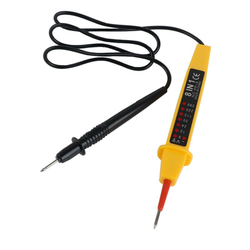
Used to have a voltage tester in the eighties/nineties.
Styled like the one in the picture but with bigger insulation, neon lights and range up to 1000V.
The screwdriver with neon was always in the pocket of my overall along with pen and markers ????
Only used the screwdriver for tightening little screws (telecom wires).

-
And what about volunteers in Thailand ?? They cost you nothing and work for free mr PM.
-
7 hours ago, Yinn said:
New TVF thread......
Dual pricing Pattaya Indian Restaurant. Tourist Scam
Discount only for farangs ????
-
4 minutes ago, Metropolitian said:
the dangers of a test screwdriver
I've encountered a 'failed' test screwdriver where the resistor + neon combination was turned around and the spring bypassing the resistor (which was in fact inside the spring) .
Yes that one was not good
-
 1
1
-
-
2 hours ago, sometimewoodworker said:
You missed that I talked about the dangers of a test screwdriver or you clearly don’t understand how a test screwdriver functions. It has a resistor and a neon, it requires you to complete the circuit by touching the metal end cap. One failure mode for a resistor is a dead short and since a neon lamp is also has an extremely low resistance at over about 80V you can get a full mains voltage shock which can kill.
The percentage of failing resistor that goes dead short is very small near nihil.
They can short, but on high voltage and arcing caused by the loss of insulation (cracks).
I wouldn't worry that much about a resistor that fails that way.
More concern are needed with capacitors which really can short when they fail.
Another story is with overheated resistors, when they burn the material inside the resistor can carbonize and then conduct electricity.
In a test screwdriver the change of that to be happen is also zero.
-
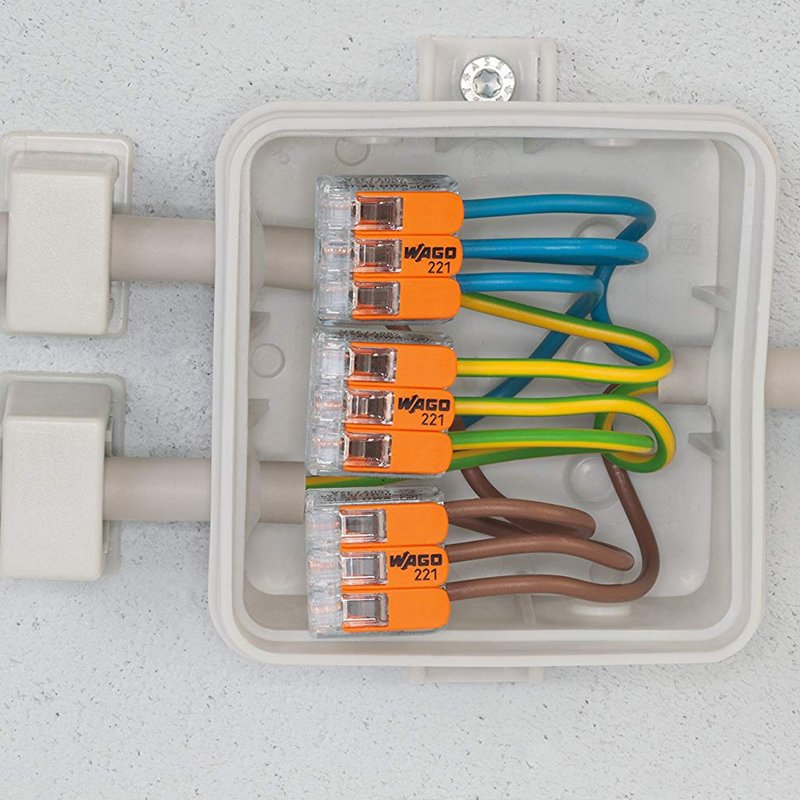
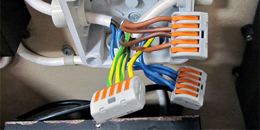
8 minutes ago, Polarizing said:
Do you know what these 3 conductors (3 holes) are used for? Do I need them and if so, I want to read more about them. Where can I do so?
Or do I only need the the two holed version?Wago is a brand, but they were the 'inventors' of the standard of the springclamps
https://en.wikipedia.org/wiki/WAGO_Kontakttechnik
It's effectively a products where you can connect wires together (even single cores and stranded wires) and without using screws.
One block connects all wires together. You need separate blocks for other wires.
The two hole versions are useful for 'connecting' stranded wires with single core wires.
Three hole versions for taps and four and more for central bindings.
They are mostly used in conduit boxes.
The wireclamps with the orange lever are a new thing.
I used to work with grey Wagos , later they came in orange colors.
-
2
-
-
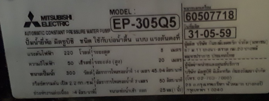
And to interpret the nameplate..
Mitsubishi Electric
Model: EP-305Q5
S/N: 60507718
Date of production: May 31th, 2016
Voltage: 220 Volt
Freq: 50 hz
Power: 300 watt
Switch turns on pressure at 2.2 kg/cm2
Pumping power > 4 liter / minute
Suction distance 8 meter
Pushing distance 20 meter
Transportation flow to reach 14 meter distance , 45.94 liter/min
Transportation flow at 2 meter distance 50 liter/min
Pipe diameter 25 mm (1 inch)
Then some address information from the company Mitsubishi at the Bangna-Trat rd. in Bangpli and phone numbers.
-
1
-
-
2.1 and 2.8 for the Q5 as yours is and 2.4 and 3.0 Kg/Cm2 for the R version of the EP-305
Some information: (And service manual as attachment in this post)
-
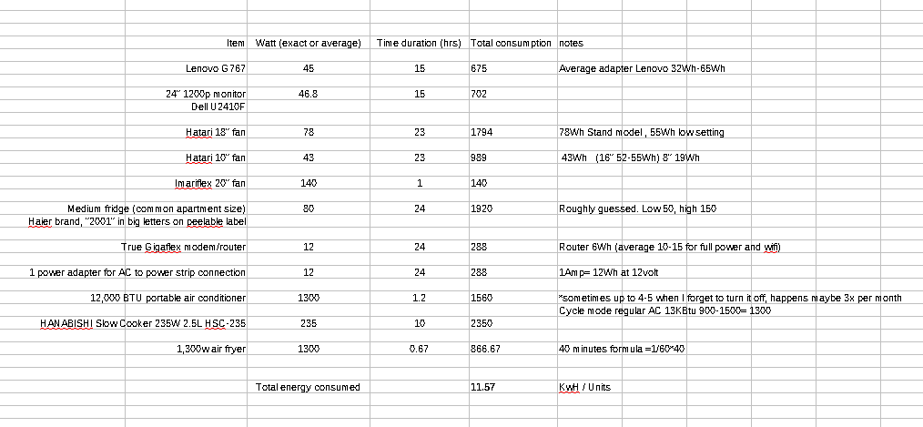
^^^ These are 'worst case scenario' , eg the appliances running on the highest settings and full power for the adapters.
It is still possible that the average would be around 8-10 units / day and the fridge using a little bit more then he used to.
Is the fridge yours? I've rented a service apartment years ago, which included bed table and fridge. My bill were high, and the fridge was the problem. Got it changed by the apartment owners and my bill lowered drastically.
-
- Popular Post
6 hours ago, Hal65 said:@MetropolitianYou are right about the fridge. damn. now i have to figure out how to isolate its effect alone while still being able to use my computer.
Maybe unplugging it at night is the answer?
Regarding your second suggestion, here is my usage per suspect:
<...cut... >
Well... check the calculation and the result...
-
3
-
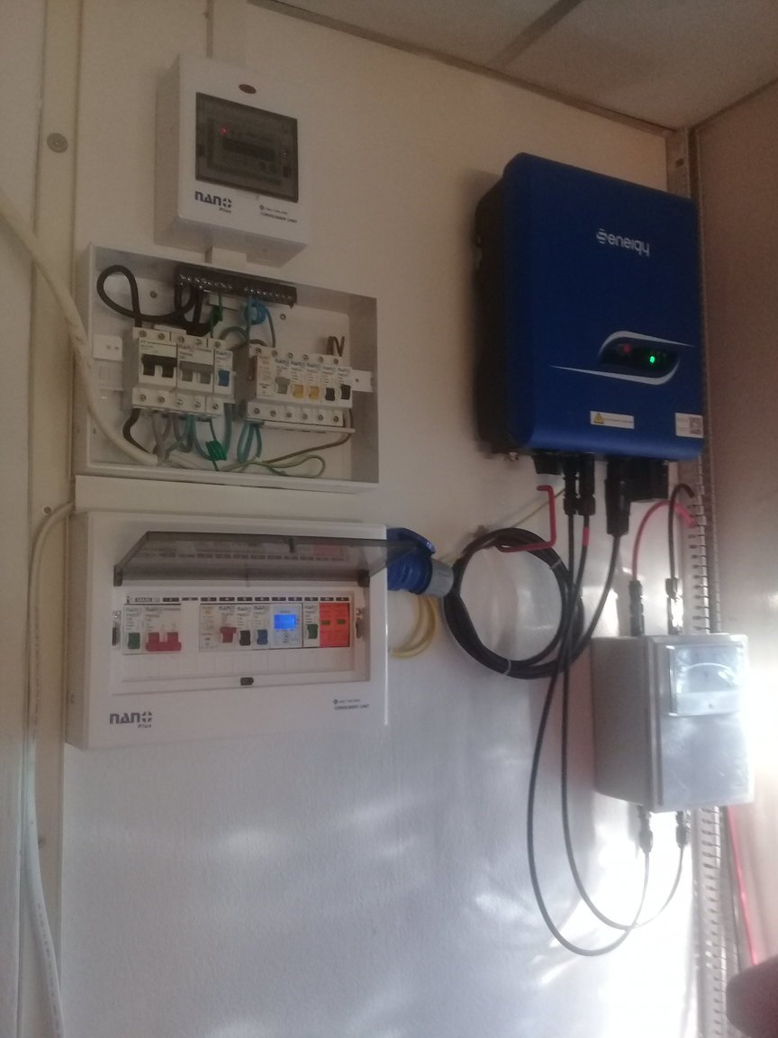
3 hours ago, tedel said:
@Metropolitian The solar inverter need all 3 phases to work
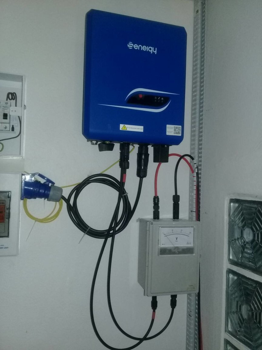
@Crossy MCCB i can use the one from sqare d load center; what i dont like about the schneider is that they have this plug on system which is fine if u use their mcb, but once u need for example pv export power meter its all din, so need separate box. I have a separate pv DC box with din rails but didnt want to mix ac with dc inside one box. Thats why i was thinking rework it all, AC box with din rails. Another thing is I was checking schneider square QO rcbo's they seems to be type AC only; i have a lot of electronic at home and type A would be much better for that ; or am i wrong ? I will make tomorrow my current electric diagram maybe it will help us better understand; thanx for helpMaybe move the dc part to near the panels and use the dc box as ac box.
If you are using surge arresters, it's better if they are close to the panels. If the distance between the panels and the inverter exceeds the 10 meter then it would be better to use surge arresters at both ends of the line.
I have here 3 CU's grouped together. One is for the AC side of the inverter (And a few other MCBs for that side of the room) and the others are for the mancave and the rest of the house.
The DC side I mounted inside a enclosure a DC breaker and two surge arresters and on the front an DC voltmeter.
Old picture from the moment of installation:
-
6 hours ago, bankruatsteve said:
Not sure that can be done in a Square-D box. (?)
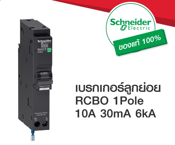
Yes it can, with this:
And as I understood in the post from the OP is that he has a 24 gangs load center and using 21 Square D breakers.
Which then I assume that he still have 3 free slots.
Of course he can have more of those RCBO's but then that would mean he has to take out a CB to make room.
-
7 hours ago, Polarizing said:
I have just opened up a socket and found out that the the green wire is connected to N and the white wire is connected to the Earth symbol. Blue is in L, everywhere in my home blue is the live wire.
Am I safe to assume neutral and ground are reversed? Or should I do some additional tests?First I have checked your CU, a split unit that is.
The wiring is very neat, only the coloring... well.. not according the standard but we will leave it at that.
The installers even used a nice coloring ring at the mains input. In your location Blue is hot and high as the sky and White is the neutral, Green is the right one and is Earth.
One thing about the wiring in your CU, I do see -one- brown wire, it is used in your case as neutral wire, do you know where it goes? Has it a right 'marking' at the end point? (white tape or marking 'N' )
Now your outlet. If the green wire is connected to the N and white is connected to the earth symbol. Then yes, according to the setup in your CU, this outlet is wrongly, not badly, connected. I can wildly assume that this socket is on the 'unprotected' side of the CU. If this socket was on the RCBO protected side, then it would trip as there would then be imbalance between the L and N at the RCBO.
Have you checked other outlets and their wiring?
-
2
-
-
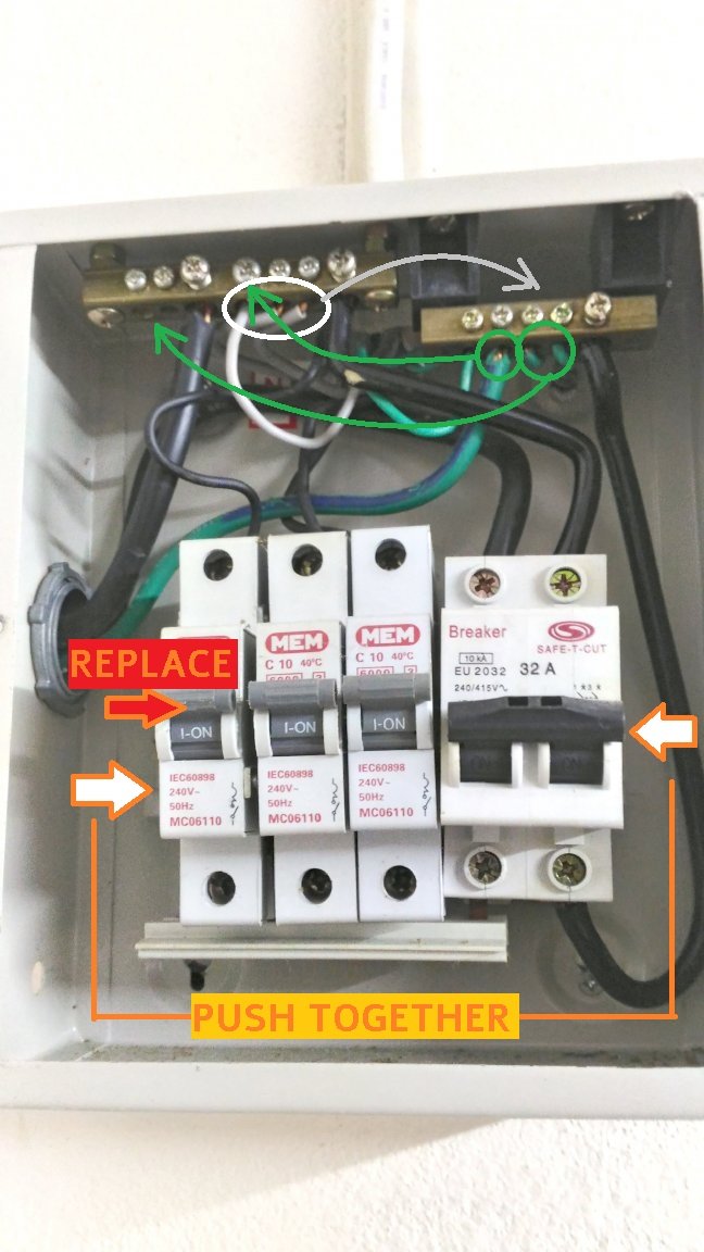
You can choose from either thinking about adding a STC box, which is not very big, which can be setup to protect one phase, but as you have a device that uses three phase I don't think it would be happy loosing one phase but not sure I wouldn't go for that solution in your setup without knowing if the inverter can work on two phases or not. ( @Crossy ? )
For your setup the best is, without 'trashing' a CB, to add three RCBO switches and connect the groups that you want to protect on this. (outlets, kitchen and/or outdoor pump..)
You have populated 21 gangs and the CU has room for 24.
-
Maybe we need to look to a different view. The usage of now is the 'new normal' and before it was a 'faulty calculations'.
We can try to help you calculate the average usage if you can give us a list of all the appliances and how long you are using them.
That means, we need to know how many watts they are using, product names and type numbers would help us.
-
7 minutes ago, Hal65 said:
Well, I would say if it slows to barely moving with everything else turned off, the fridge was already tested.
I know that answer will frustrate the highly detailed types but the goal isn't to get the meter to stop dead, it's to figure out why it's spinning so much as things are added.
My hypothesis is the wiring has degraded. I'm planning on a move to the neighboring unit.
If still too high I know that one of my appliances has gone bad. Possibly laptop, laptop charger, monitor, fans, AC, or a lesser used/weaker current item.
If with everything 'normal' connected, eg. the aircon only one hour and watching tv / laptop.
All that, with only the fridge turned off.
And tomorrow the used units is still around the 11 , then we can say the fridge is 'okay'.
Maybe the fridge is one of the appliances that has gone bad...
A fridge has a start-stop-start-stop pattern, one that goes bad can be start and not stopping for 'rest'. Which uses way more energy over time.
-
It could possibly your fridge.
I looked in the previous pages, and one thing I noticed is that you didn't try to turn off the fridge during testing.
Turn off your fridge for one day and come back with the meter results.
Another possibility that I was thinking is that you are looking at the wrong meter, 10 units is about the usage of the hallways and stairways lights and elevator at the service apartment where I lived in years ago.
But I read that your meter was slowing down upon testing, and eventually got replaced, so time to look at your space.
The fridge.
Tell us the outcome.
-
And remove the sticker with 'N' from the back plate ????
-
1
-
-
5 hours ago, johng said:
Here is how they wired mine.
????♂️ The first breaker looks like it was broken and now only held together with screws.
The big green wire, if connected with the ground earth rod, to be moved to the earth bar the one with the big screw.
This is for sure, no doubt from my side.
BUT the remaining green wires -and- the grey wires... I don't know how they are wired in the sockets on the walls.
If in the sockets the grey wires are used as earth and the green wires are neutral. Then you only need to move the big green wire in the CU if that wire come from the earth ground rod.
If in the sockets the grey are connected with neutral prongs and the green used as earth, then move the wires according the picture below.
-
 1
1
-
-
- Popular Post
- Popular Post
Just now, Metropolitian said:Now in the current setup you need to do two things;
- Move the neutral main wire to the earth busbar and a wire between the earth busbar to the Neutral IN at the bottom of the main breaker.
DANGER.
BE AWARE : That the incoming main wires are connected directly to the grid, there is nothing that protects you.
Only do when you are sure, which means measure measure measure and even then not believe the measuring equipment blind.
With a proper test (neon screwdriver which glows on contact with a live/hot wire or using the right gear) you can tell which one is real live wire. (Always assume that stickers are never 100% telling the truth)
Never touch it. Only the neutral wire need to be changed.
In doubt, even the slight percentage of doubt, let a spark do it.
Everything behind the main breaker can be isolated and are more 'safe' to handle with.
(assuming there are no children there and the wife is sent to the shopping mall
)
-
3
-
1
-
- Popular Post
- Popular Post
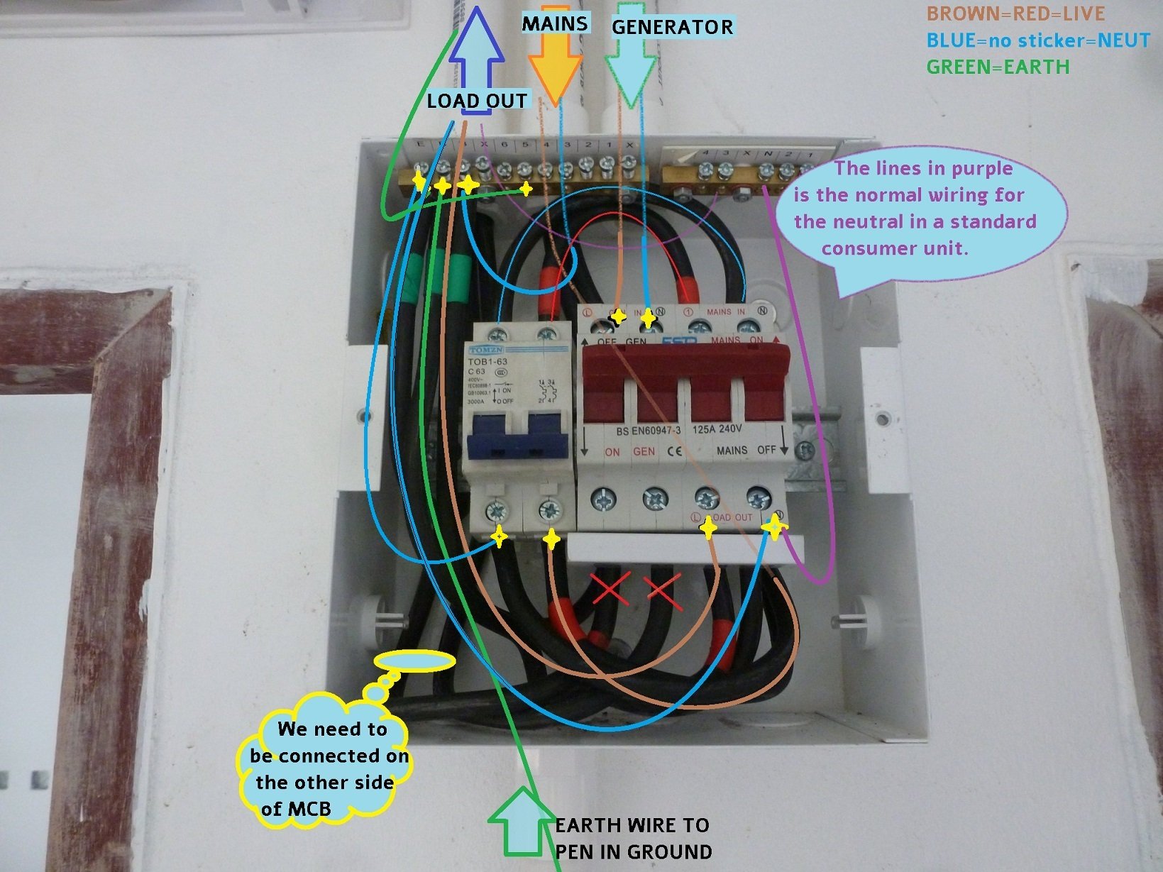
- This ESR Changeover switch, which can be assembled as crossover or changeover, has double-row busbar under it. So only one output, the Load Output.
- The big busbar is connected with the iron casing, this is the earth-busbar.
- The incoming neutral need to go to the earth busbar and then to the main breaker.
- Normally the N-out is connected to the neutral busbar (which is isolated from the iron casing) but in this setup only one wire so you can skip using the neutral busbar. (the purple lines is how the neutral wires usually are wired.
- I can see in the wiring that the wires that goes to the other consumer unit and the wires that goes to the generator shares the same pipe, right? In the drawing for conveniently I separated those wiring for easy understanding how the wires are wired.
- The earth ground rod goes is coming from below and is wired right.
- Make sure the generator set has a proper MCB.
- DO NOT connect the neutral wires to the earth bar in the other Consumer Units.
- Only in this unit the Earth and Neutral are linked, which make sense as the ground rod wire is also there.
Now in the current setup you need to do two things;
- Move the neutral main wire to the earth busbar and a wire between the earth busbar to the Neutral IN at the bottom of the main breaker.
- Move the wires from the generator, and connect it on the top with the label GEN-IN
The Earth busbar:
E. Connect the earth ground rod here.
B. Connect the -INCOMING NEUTRAL- here
B. Connect a Neutral Bypass from here to the N-IN at the main breaker.
6..1 Connect the Earth wire that goes to the other (Consumer) Units here. (Don't forget the gen.)
-
3
-
1
-
Wiring in both is wrong.
Give me some minutes to come up with the right drawing.
Don't turn it on yet @Cashboy
-
1
-

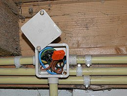


How to wire this?
in The Electrical Forum
Posted
Can you take a picture of the whole setup? Where are the other wires going to (socket?) and where are the switch and unearthed socket located?
This would help us with telling how to pull cables and locations for taps.
For the switch/unearthed socket in the photo. It looks like the one with the black tape marks are the live wire, which are taped off from a blue wire somewhere in the attic/walls, and the thinnier white wire (1.5sqmm) is the real neutral. But very bad practice.
Do you have testing gears? Like a neon light test probe/screwdriver?