Fruit Trader
-
Posts
1,406 -
Joined
-
Last visited
Content Type
Events
Forums
Downloads
Quizzes
Gallery
Blogs
Everything posted by Fruit Trader
-
For most gensets fitted with an ATS remote start port, any high current switching will be handled internally. If this were not the case, the fuel and crank relays of the Smartgen controller are rated at 16A which is more than enough to handle a starter solenoid and fuel valve. This project is of interest to me because the brother-in-law plans to use one of the Chinese multifunction genset controllers in one of his up and coming work projects.
-
Electric Vehicles in Thailand
Fruit Trader replied to Bandersnatch's topic in Thailand Motor Discussion
Masculinity is definitely on the decline, not sure about EV owners though . . .
-
I chose Aux output 1 (programmable) for the start relay because its contact is already on the 12v+ line as shown below at the internal diagram. What I am not so sure about is the how this particular diesel genset handles pin 4 (start relay)
-
Yes it is but some ATS include an electronic control module or timer relays capable of starting the genset via a dedicated ATS connecting cable. Not all gensets have this connection available and require some mods to the start circuit to add automation. Like you I prefer to think of them separately and not combine under the ATS label.
-
My two cents :- Genset Fuel to controller pin 4 Fuel Genset Crank to controller pin 5 Crank Genset Start relay to controller pin 6 Aux output Genset 12V+ to controller pin 2 B+ Genset 12v- to controller pin 1 B- Emergency stop input 12V+ on controller pin 3 to cut crank and fuel power. Wiring of power transfer device and power monitoring to controller.
-
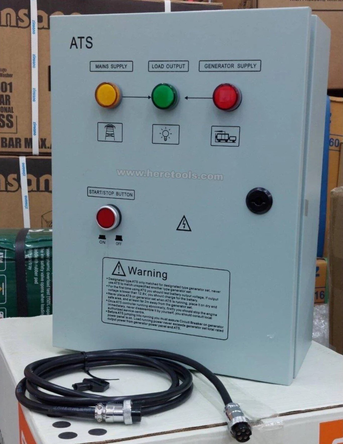
The genset shown is ATS ready which in this case means it has a dedicated connector for ATS control. Normally one would purchase a compatible plug and play ATS similar to the photo below but it appears the OP has chosen a DIY route using a multi function controller that can handle all functions and monitoring of backup power. Identifying the exact function of each ATS connection at the genset would be my first call. The description shown is a little vague. Plug & Play ATS
-
Engaging with Russians during wartime in Thailand?
Fruit Trader replied to Jingthing's topic in ASEAN NOW Community Pub
Sanctioned Ivan (YouTube name) is not your typical Russian. He grew up and went to school in Ireland before moving back to Russia where his work got hit by money transfer sanctions. I first picked up his story at a U.S. car dealer channel where he talked about his dreams of moving to the U.S. His YouTube channel carries on the Russia, Turkey Thailand venture. -
Either the electronic steering has lost the plot or its artificial intelligence has decided to adopt Thai driving habits.
-
Electricity costs for remote controlled electric sliding gates
Fruit Trader replied to scorecard's topic in IT and Computers
A 10 year old gate motor will very likely require an upgrade to facilitate additional remote control methods like Bluetooth or Wi-Fi control via mobile application. All the required information can be obtained by calling PAT automation (info in previous posts) with model number of the gate motor. They will cost replacement remotes and any WiFi/Bluetooth upgrades available. Most PAT gate motors use common 433 MHz rolling code remotes. Most gate motor installers should have a suitable replacement for around 400 Baht . -
Electricity costs for remote controlled electric sliding gates
Fruit Trader replied to scorecard's topic in IT and Computers
https://bltassociates.co.th/ -
I think same or some other part of the fan motor. These noises often begin after warm up or from resonance within a speed range.
-
Electric Vehicles in Thailand
Fruit Trader replied to Bandersnatch's topic in Thailand Motor Discussion
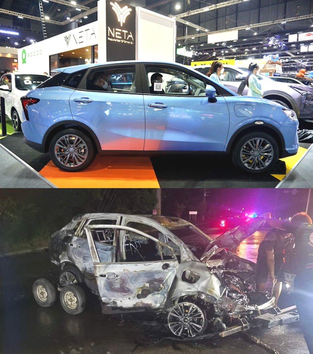
Just a post for people to sharpen their observation skills, as for the authenticity I have no idea other than the accident photo was taken somewhere in Thailand. -
Electric Vehicles in Thailand
Fruit Trader replied to Bandersnatch's topic in Thailand Motor Discussion
Topic title = Electric vehicles in Thailand. Partial original post = Do you know of any breaking news about EVs in Thailand? If so post here. -
Electric Vehicles in Thailand
Fruit Trader replied to Bandersnatch's topic in Thailand Motor Discussion
For the observant :-
-
Sometimes one must think outside of the box and the ideal world it might portray on the inside. LED tube manufacturers have attempted to reduce risk of electric shock for the thousands of people who purchase and replace lamps every day of the week without the need for specialist training and test equipment. But in the case of LED tubes with removable safety tab, what happens if these people decide to remove the tube after the tab has been discarded? This is where risk assessment ends for some manufacturers while others have gone one step further and included a permanent isolation switch at the end of the tube.
-
-
LED tube plastic safety tabs. Double ended tube fittings have a live end and a neutral end. If the live end is inserted first there is risk of electric shock from the exposed neutral end before it enters enters the socket. The plastic guard tab isolates pins at one end thus eliminating the risk. The tab is removed once both ends of the tube are securely located in their sockets.
-
There are two models 500 and 550 one uses a AC motor to drive the gate the other DC. If your info is correct your gate is the 500 driven with a AC motor. Both of these models use DC signals at the limit switches but different style of switch mount which is why the listing has selection for 500AC and 550DC. PS The DC motor versions provide improved control of the gate and the ability to add battery backup on some models.
-
Both BSM and the Foresee F500 drive the gate gearbox with an AC motor. These AC motors are powered from the 220V side of the circuit board. In another area of the circuit board there are DC electronic circuits taking external inputs from limit switches etc which are then processed by logic control to decide what happens at the 220V AC motor side. Almost all gate controllers use low voltage DC signals in the limit switch circuit. The control board is not bothered if these signal come from a mechanical micro switch or magnetic reed type. The difference between switches in the links you provide is one is operated mechanically the other with magnetism.
-
Thats a good suggestion if the correct centre off switch arrangment is chosen. Problem is the limited space inside of these gate motor enclosures as I mentioned in an earlier post.
-
You have ordered a magnetic limit switch for the BSM brand gate motor. Apart from the outer case it's pretty much the same as what you originally suggested from AliExpress. AC in the product description does not mean the switch is an alternating current version. You will need two magnets and mounting brackets which I guess you have ordered separately. Like most of the magnetic gate control switches, the BSM version you have ordered is nothing more than two reed switches soldered to a circuit board as shown below. Inside the BSM magnetic switch module
-
What does the average British expat think of Tommy?
Fruit Trader replied to Kinok Farang's topic in ASEAN NOW Community Pub
I am not a Brit but have read a lot in the news about Tommy Robinson. First heard about him at the Oxford Union channel, interesting character. -
Motorbike Ban in Pattaya Underpass Sparks Heated Debate
Fruit Trader replied to webfact's topic in Pattaya News
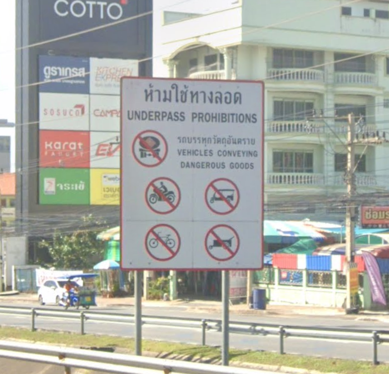
The large blue signs on Sukhumvit Road mean after the intersection you are on a motorway. Motorcycles are not allowed on motorways so there should be no need for additional warning. But, as you pass through the Pattaya toll gate coming from Chon Buri there is an entrance to the motorway without any blue signs and an incorrectly positioned no motorcycles sign. In other words you drive onto the motorway then get a warning. The entrances to Thailand's toll free motorway sections are a mess of contradiction. Last time I passed through the tunnel there were warning signs on the right side. Its amusing to watch cars and trucks dodging slow moving food seller carts sneaking through the tunnel.
-
The control board has relays to control the motor already! The relays control motor direction while other circuits on the 220V side provide soft stop to limit gate hard closing. Inputs from limit switches tell the controller when to slow down and stop the motor. The controller can also use its relays to stop the motor if safety devices are triggered or excessive motor load detected. It's not really that difficult.