


007 RED
-
Joined
-
Last visited
Posts posted by 007 RED
-
-
20 hours ago, Encid said:
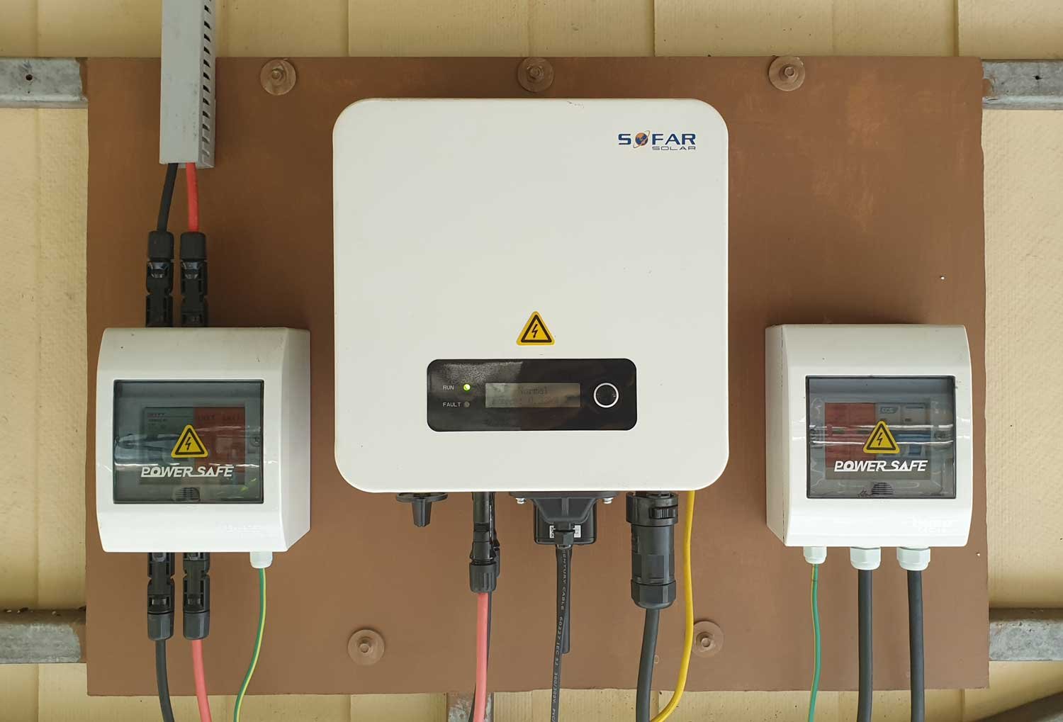
@007 RED has a 2.2kW Sofar GTI
I installed my Sofar 2200TL-G3 inverter 14 months ago and since then it has happily produced 3.22MWh which has reduced our electricity bills by approximately 75%. Without wishing to speak to soon ????it has been very reliable and not thrown any wobblies. We had a power outage a couple of weeks ago which lasted for about an hour, the first that I can remember in a long time. The inverter shut down (anti-islanding mode) as expected and 'booted' back up again without any problems once the grid power had been restored.
If I was going to replace the current inverter for a larger one, which I'm not considering, I would definitely go for another Sofar.
FYI... The warranty, which is subject to normal T&C, is for 5 years. The Thai company that I purchased it from advised that if there was a problem during the warranty period I should contact them and if they have one in stock they will send a replacement. If they have no stock they will get replacement from manufacturer which may take 15 to 30 days.
-
 2
2
-
-
- Popular Post
I just watched a short video on BBC World News concerning the sinking of this ship. The video showed the ship listing heavily on its port (left) side. The video looked as though it was taken from a rescue helicopter's FLIR unit.
I have taken a screen shot (below) from the video. I would seriously question what looks to be possible damage midships below the water line.

If this is damage, then that would explain why the ship initially listed to the starboard (right) side as water flooded into the lower compartments and then the swell pushed it over to the port side as seen above.
-
2
-
 3
3
-
- Popular Post
The past month (16 Nov - 16 Dec) has been really naff so far as my small scale solar system production was concerned. The weather has been well below par with many days having lots of clouds. Even when there were minimal clouds, it was very hazy. I also noted that the sun is now much lower towards the Southern horizon most of the day which also hinders solar production.
Below is my production graphs for the billing period Nov -Dec. which clearly shows that I failed to meet mt target of producing 75% of our electrical needs ????.
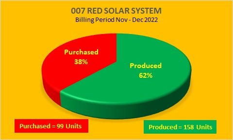
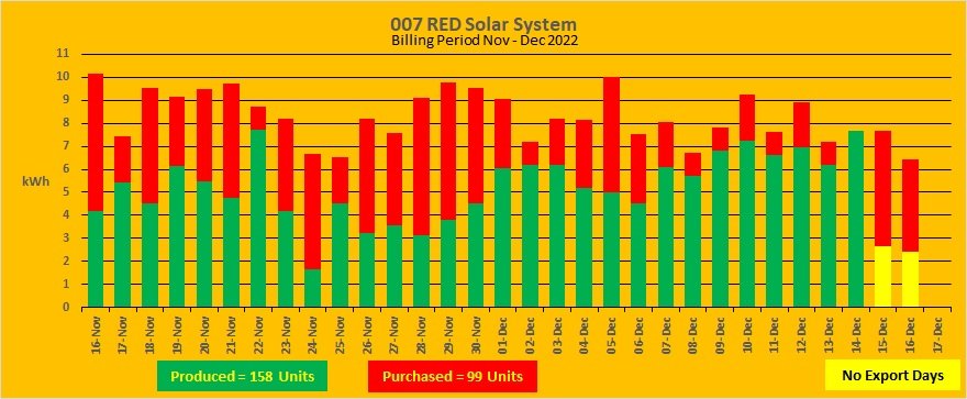
Note: From the above graph it will be seen that on the 24th November the system only managed to produce about 1.5 units and I needed to purchase 5 Units from the PEA to meet our needs. On that day we had very heavy clouds and it poured with rain for most of the day (lot of local flooding as a result).
-
3
-
 1
1
-
Further to my previous post above, I did a 'reverse test' this morning e.g. the system was in normal EXPORT mode and I activated the NO EXPORT switch.
Looking at the meter prior to activating the NO EXPORT mode the meter was happily spinning backwards, albeit slowly due to a lot of haze. Looking at the meter soon after activating the NO EXPORT mode the meter started spinning in the normal direction (anticlockwise). Looking at the system monitoring facility, the inverter clearly showed that it was aware that the CT was connected (NO EXPORT mode).
I left the system in the NO EXPORT mode for about 10 minutes and then went back into EXPORT mode. The meter was spinning backwards again, indicating that the inverter was now allowing excess power to feed into the grid.
So I think that it is fair to say that my Sofar 2200TL-3G GTI is capable of knowing when the CT is, or is not, connected and reacts accordingly by allowing or preventing excess power being exported. Thankfully there appears to be no adverse affects resulting from my little tests.
Please note that my observations may, or may not, apply to other makes/models of inverter.
-
1
-
1
-
-
On 11/28/2022 at 3:00 PM, Crossy said:
Just pull the plug and see what happens, nothing will get damaged.
The worst that may happen is the inverter throw an error "CT disconnected" or something like, but I suspect it will just go to full chat.
I do see that our Sofar, won't go to full power if it's been limiting and has shut down one string, but we turn our CT on/off at midnight so everything is asleep anyway.
If you don't go to full power try turning the inverter off then on again with the CT disconnected.
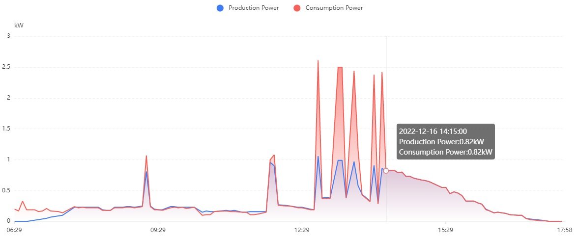
Today was meter reading day (16/12/22), so my small scale system has been in NO EXPORT mode since yesterday just in case the meter reader came early.
The meter reader arrived at 14:10pm, so a few minutes after his departure I flicked the NO EXPORT switch back into EXPORT mode and looked at the meter. The disc was merrily spinning backwards again.
As shown in the screen shot below from the system's monitoring facility, the inverter appears to have picked up that the CT was disconnected at approximately 14:15pm and thus allowed power to feedback into the grid. FYI... I switched on one of our AC units for approximately 10 minutes at around 14:30pm and the graph below doesn't show any consumption spike which I would have expected if the system was in NO EXPORT mode. This confirms that the inverter was not getting any consumption feedback information via the CT.
Tomorrow I will do a reverse test e.g. allow the system to operate in the EXPORT mode in the morning and then throw the switch to NO EXPORT in the afternoon and see what happens. Hopefully no magic smoke ????. I will report back.
-
23 hours ago, 007 RED said:
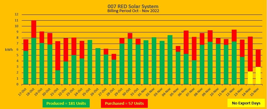
Yesterday (15/11/22) was meter reading day, and we were presented with a massive bill for 57 units amounting to 239.86 THB, which equates to 4.2 THB per Unit. This is the lowest that we've had since installing our small scale system some 13 months ago. The system appears to be performing well given the fluctuation in weather conditions during the past month, as shown in the graphs below.
Just to confirm.... The 4.2 THB per Unit figure which I quoted above is based upon the final charge that we have to pay the PEA and includes the total energy cost + monthly fee + Ft - Government discount + VAT.
If I just used the energy cost (185.15 THB) for the 57 Units, then the unit cost would equate to 3.25 THB per Unit.
I note from previous bills which have been higher, the energy cost per Unit has been higher e.g. 884.12 THB / 244 Units = 3.62 THB per Unit.
FYI ..... I have attached below a copy of the 15/11/22 bill.
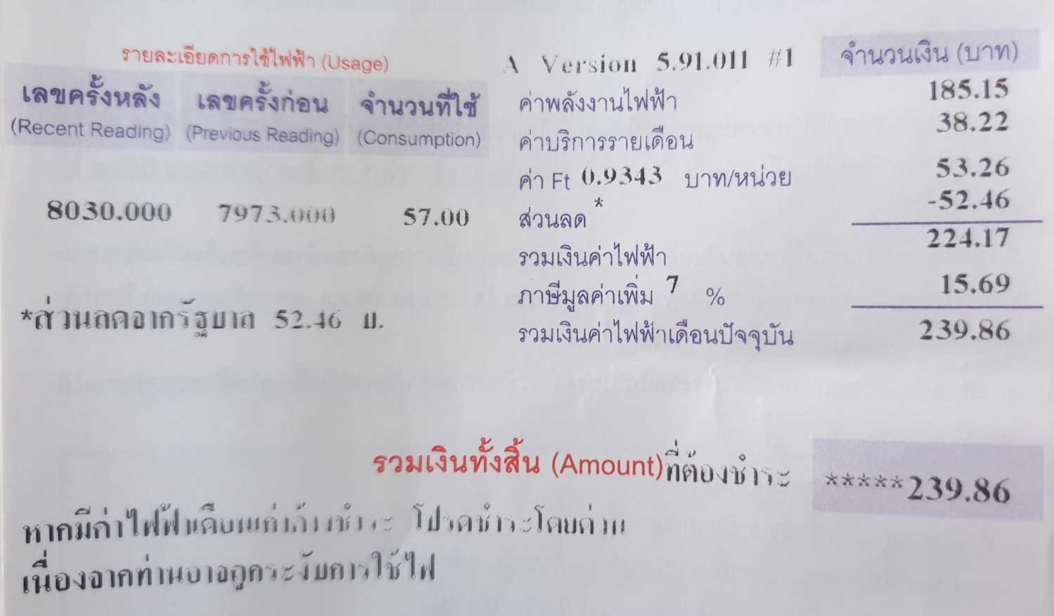
What is the Ft = 0.9343 THB/Unit ???????
-
- Popular Post
Yesterday (15/11/22) was meter reading day, and we were presented with a massive bill for 57 units amounting to 239.86 THB, which equates to 4.2 THB per Unit. This is the lowest that we've had since installing our small scale system some 13 months ago. The system appears to be performing well given the fluctuation in weather conditions during the past month, as shown in the graphs below.
-
6
-
- Popular Post
On 10/23/2022 at 7:37 PM, JAS21 said:If you were to be given a ‘no export’ meter…how many units (kwh’s) do you think you would have to pay for in one month?
An interesting question. I think it’s not “if”, but “when”. That said, as TIT the “when” could be any time from tomorrow or sometime in the next millennium. Who knows?
My small scale system (4 x 415 W panels connected to a 2.2kW GTI) in theory should be capable of producing 1.66kW under laboratory conditions. However, given that we are living in the real world, the system is more likely to produce about 1.2kW under good sunshine and assuming 6 hours of decent sunshine a day, the system should be capable of producing around 7 units a day ????.
Although we have a range of household appliances, including a couple of air conditioning units, my wife and I are somewhat conservative electricity users. Prior to installing the solar system, PEA billing records for the previous 2 years indicated that we were using on average 10 units/day. So when I designed the system, I did so with the objective of the system being capable of producing a maximum of 75%, or 7 units/day, in order to avoid any risk of producing negative meter readings.
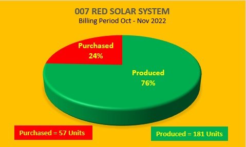
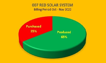
The graphs below for the current billing period shows that our small scale system is currently producing 65% of our needs, leaving us to purchase 35% from the local PEA.
It should be noted that weather conditions this month have been mainly overcast with the occasional heavy downpour, hence the somewhat lower than hoped for production yield ????.
As I type this post, the monitoring facility is showing that the solar panels are producing 1.24kW and hence my meter is merrily whizzing around backwards due to the nice blue sky and nice bright sunshine ????. Obviously if the meter were to be replaced with an electronic type thus preventing backwards spinning, I will not be able to ‘store’ my surplus power in the grid for use when the sunshine disappears behind a cloud.
I have noticed from the system’s monitoring facility that on the couple of days when my system is in the NO EXPORT mode prior to the meter reader coming, the system appears to almost keep ‘pace’ with our needs, except for short periods when we are using the shower heater, water pump or washing machine.
I envisage that if/when the PEA install an electronic meter, because we are relatively low electrical users, we will only need to purchase a few additional units a month and I may well then consider installing an additional solar panel to compensate for the loss of 'free' storage convenience.
Due to the high costs associated with hybrid systems, and our low consumption, I have no plans to go down the ESS route.
-
2
-
1
-
19 minutes ago, Bandersnatch said:
I have just finished reading the document - thanks for sharing @007 RED I saw that the FiT listed was 6.96 baht/unit. This is the rate from the original scheme. I know some people who are still being paid this rate and are very happy about it. I note the date quoted was 2013. They closed the scheme to new applications and for some time the whole FiT was in limbo until they introduced a new scheme in 2017 at the new ฿1.68 rate and then the current 2.2 Baht/kWh.
I note it states the following about solar installer - just wondering if this has been carried across to the current scheme:
“A person qualified to install solar PV rooftop system should be a person certified by and
registered with the Department of Alternative Energy Development and Efficiency or a person with relevant license for professional practice”I was aware that the document relates to the 2013 regulations but I think you'll find that the 'rules & regs' are still the same, its just that they have amended the rates paid for FiT and the maximum amount of power feed-in that the PEA/MEA can allocate to individual providers.
And yes, you also need a person who is professionally licenced to certify that the roof will support the weight of the solar installation ????
-
1
-
1
-
-
18 hours ago, Thaifish said:
1 year 7 months.
16 hours ago, Crossy said:In the light of this latest announcement, it could be time to get out the sharp stick again ????
Assuming that the installer, or yourself, submitted the application in the first instance and all the required paperwork etc. I think it's about time to 'rattle a few cages' and collect some compensation for loss of income.
I've attached below a PDF translated copy of the 'ERC Regulations on Thailand's Solar Rooftop Programme'. You will see from this document that if your system has been approved and the PEA have failed to pay you for power that you have generated, and you have complained to them, then you can escalate the mater to the the ERC HQ, who will investigate and give a ruling. If they find in your favor they will instruct the PEA to pay you what they owe plus interest.
Obviously you will need to submit such a complaint in Thai and provide good backup evidence to support your claim.
It may be worthwhile trying. Good luck.
-
2
-
-
Congratulations, a really nice installation. As you mentioned, l would definately raise the battery off the floor to avoid any 'rising damp'.
-
1
-
-
2 hours ago, a340bangla1 said:
Hi there
not DIY, but done by an installer:
Huawei SUM2000-5KTL-M1 5.0Kw, 3 Phase inverter and totally 14 Jinko PV panels 470W, no battery as yet, cost was slightly below 200 KTHB all in.
Running with 0 export most of the time. It is still slightly hazy but we are getting close to 5 kW at the moment.
I would have to agree that 3 x 1-phase inverters might have been better due to 1 phase dropping out frequently. At the time of decision I did not think about this possibility but I guess it would have made the setup more expensive and complicated.
"no battery as yet"
Just a heads-up...... I seem to remember another forum member who has had a Huawei inverter installed discovered after the fact that Huawei some how tie you into using only their batteries, which then turned out to be a very expensive option. Hope I'm wrong for your sake.
-
1
-
1
-
-
- Popular Post
Today, 6/10/22, celebrates the 1st ‘birthday’ of my small scale grid tied solar system, so now is an opportune time to take stock and assess its performance during the past 365 days.
Background
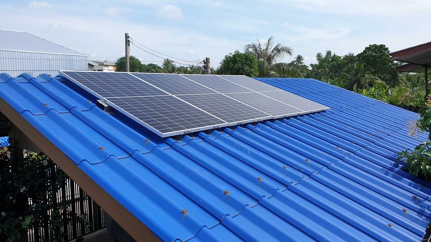
The system comprises 4 x 415W half-cut mono panels connected in series to a 2.2kW Sofar grid tied inverter. The system was a DIY project, so there were no labour costs, just my time and effort. The total cost of the hardware worked out at a tad over 28,000 THB.
We (my wife and I) consider ourselves to be ‘conservative’ electricity users with our bills, prior to installing the solar system, averaging around 1,000 THB per month.
When I designed the system, I decided that the main objective of the system would be to reduce our electricity bills by approximately 75%. This would ensure that we didn’t get into a situation where the system generates negative readings when the meter reader calls.
Under laboratory conditions, the 4 x 415W solar panels should be capable of producing 1.66kW, but of course were not living in a laboratory. In reality, the panels are more likely to produce around 1.25kW in good sunshine. Therefore, assuming 6 hours of good sunshine a day, the system should be able to produce (1.25 x 6) 7.5kWh a day, which is the figure that I considered to be the target for the system.
What has the system achieved during its first year of operation?
According to the system’s monitoring facility, it has generated 2,590kWh during the past 365 days, or an average of 7.1kWh per day. Attached below is a graph illustrating what the system has produced, and what we purchased, since 6/10/21 to date. I have also included what we purchased during the 9 months prior to the system becoming operational for comparison purposes.
Looking at the graph below, it may be seen that we have slightly increased our consumption since the system became operational. I'll blame this on my better half who says that our electricity is free now ????.
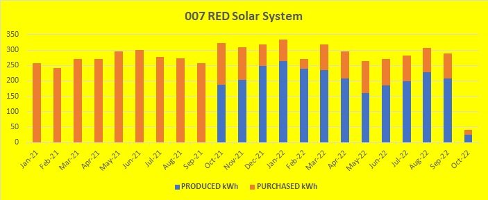
Since the system became operational it has produced approximately 70% of our household electrical needs, resulting in us only having to purchase about 30% from our local PEA. Although slightly lower than what I had hoped for, I still consider this to be perfectly acceptable, particularly given that the system was running in ‘NO EXPORT’ mode for nearly 3 weeks during May/June (See Note 1 below), and with very overcast conditions during late September/early October due to the monsoon season.
Taking the cost of electricity as being 4.2 THB per unit (See note 2 below), the system has saved us (2,590 x 4.2) 10,878 THB during its first year of operation.
Return on Investment
If the system continues to produce the same output level over the next couple of years, it would be reasonable to assume that it will have paid for itself (28,000 / 10,875) in just over 2.5 years. Obviously if the price per unit of electricity increases, then the Return on Investment will be shorter ????.
Problems
Not wishing to speak to soon ????, but thankfully during its first year of operation there have been no major problems with the system.
Shortly after turning the system on, I discovered that a MC4 cable connector (from the solar panels to the DC breaker box) was getting very warm. Upon investigation I realized that I had not fully crimped the cable inside the connector. Thankfully, this was identified/rectified before any real problems. Definitely my bad.
The only maintenance the system has needed was to clean the panels on a couple of occasions to remove dust/dirt, although I’m not sure that this had any profound effect on the system’s performance.
Will I up-grade the system?
At this stage no. I’m very satisfied with the system’s performance and hopefully it will continue to provide a reasonable daily contribution to our electricity fund. If, and it’s a big if, the local PEA decide to replace our disc type meter with an electronic one, then I will have to seriously consider increasing the number of solar panels and possibly installing a second inverter.
Note 1.
I had to put the system into ‘NO EXPORT’ mode for almost 3 weeks during May/June because the new build house opposite was nearing completion and the electrical contractor had run the supply cables from the house to the pole outside our house, which also has our meter on it. As we had no idea how long it would be before the local PEA would come to install the meter for the new house we decided to go into a ‘safe’ mode, as we obviously didn’t want the meter installer to see the disc spinning backwards on our meter.
Note 2.
The figure that I have used (4.2 THB per unit) was the average that we paid per unit during the 9 months prior to installing the system.
Note 3.
On a light-hearted note. I recall a forum member some time ago suggesting that I was “penny pinching” by saving a few Baht a day. Well, I would ask, other than a ‘Ponzi scheme’, what investment is going to give me nearly 38% interest per annum.?
If I was to put 28,000 THB into a basic bank savings account for the past year, I would be extremely lucky to get about 1,400 THB back in interest. Then to add insult to injury, whatever interest is paid would be automatically reduced by X% ‘with-holding tax’.
So, at the end of the day a Return on Investment of 10,626 THB could well be considered a worthwhile payback.
-
3
-
 5
5
-
1
-
1
-
3 hours ago, Crossy said:
It was customs who inspected it, but ...
Was it? I wouldn't be to sure. I would bet 10 2 1 that DHL opened the parcel to inspect the inverter and identify the make/model/serial # which they then checked via the internet against the declared made by the Sofar when they shipped it.
As far as I'm aware the major freight players such as FedEx, DHL and UPS have a 'special' agreement with Thai customs insofar that they initially 'act' as per Thai customs in clearing the item and determining the amount of duty and tax to be paid. They then change their 'hat' to that of 'broker' in the negotiations between the customer and themselves as 'customs' regarding the duty/tax payable. It is only on rare or special occasions that Thai Customs actually become directly involved.
Its win, win for them. They get paid to ship the item in the first place, then paid a broker's fee by the receiving customer to get customs clearance and then get a nice little percentage commission from Thai customs after they have collected the duty/tax due.
I gleamed the above information from my wife's niece who works for one of the above mentioned 'players' a couple of years ago when I imported some first aid equipment from the UK that I was donating to my local rescue foundation. In that case it was not only the duty/tax that they wanted, but import license's from the Department of Food and Drugs Administration for each item. Negotiations with them was like pulling the teeth from a tiger.
So you appear to have been very lucky.
I hope it works OK when you test/install it. Are you going to have to return the dead one?
-
1
-
-
-
 2
2
-
-
-
-
1
-
1
-
-
- Popular Post
1 hour ago, carlyai said:I thought I saw someone here who installed 3 phase solar.
I thought it was red007 but think I'm mistaken.
Sorry...... Not guilty.... I'm definitely on single phase supply.
-
2
-
1
-
- Popular Post
1 hour ago, MJCM said:Another question, this time about NO-Export
Suppose you have NO-Export turned on, and your house is only using let's say 300W, but the Panels are producing (again let's say) 1500W.
Where does those approx 1200W (difference between usage and producing) go instead of going into the grid?
As @Crossy has indicated above, it really never gets generated. My inverter (Sofar 2.2kW GTI) can be set to export from zero to 100%. I have it set to zero and activate 'NO EXPORT' a couple of days prior to meter reader visiting. During the 'NO EXPORT' period the Current Transformer (CT) which is clamped over the live wire between the consumer box in the house and the meter on the pole outside is sending feedback to the inverter as to how much power we are using in the house. The inverter then adjust itself to only produce enough power such that no power is exported thus making the meter spin backwards.
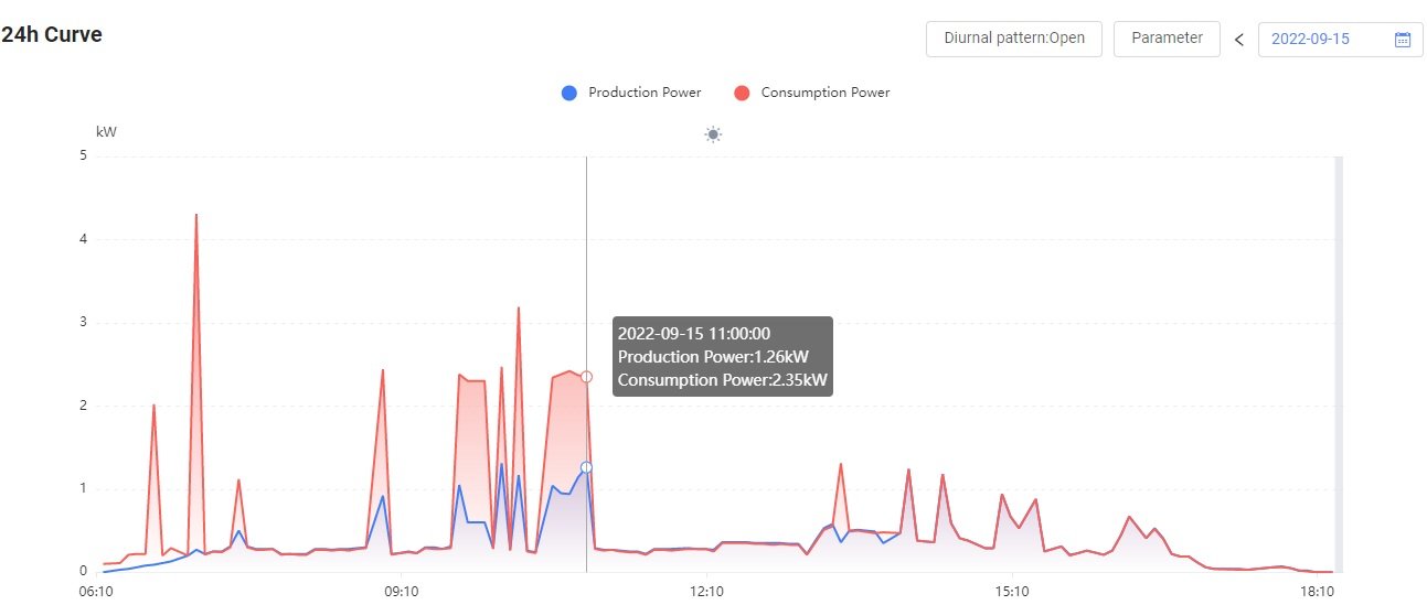
Take a look at the graph below produced from the system's monitoring facility the day before the meter reader came. The system was in 'NO EXPORT' mode, and shows power production (blue) against power consumption (red).
You will notice that at times the consumption 'hits the roof' and the system tries to match that demand but fails abysmally because there was not enough sunshine hitting the photocells. You will also see that at other times the power production equals the power consumption even when there was good sunshine (mid-day) thus illustrating that power production is matching power consumption.
-
2
-
1
-
Prior to installing our small scale GT solar system (360 days ago), we were purchasing around 280 - 300 units per month. The aim of the system was to reduce our bills by 75% thus ensuring that we never got into negative meter readings.
Like @Crossy, I weened the readings down incrementally for the first couple of months by activating the 'NO EXPORT' facility for short periods of time during the month to ensure that some 'bright spark' at our local PEA didn't notice a sudden drop in consumption,
Since the system has been operational our bills have been on average around 90 units per month, which is slightly less than I'd hoped for, or approximately 68% solar and 32% purchase.
Foot Note:
In hindsight I'm not to sure if a sudden drop in meter readings will raise any 'alarm bells' with the PEA. Prior to Covid restrictions being introduced 2 years ago, one of my neighbors (husband, wife and daughter) were living at home and commuting into BKK on a daily basis for work/university. When the travel restrictions were implemented they rented an apartment in BKK and returned home at the weekends. The whole family love their ACs which are on day and night, so their bills prior to Covid would have been substantial and there would have been a considerable drop in the number of units purchased each month once they started living in BKK. I've just spoken to the wife and she advised that they have not been contacted by the local PEA. So, no problem ????... hopefully.
-
1
-
1
-
-
50 minutes ago, Crossy said:
Movement ????
Do DHL deliver on Saturday?
YES... and if your extra lucky, on Sundays too.
-
2
-
-
2 hours ago, superal said:
Looks like a professional installation . Are you an electrician ? Also what appliances can your solar system run and do you have storage batteries for night time use ?
No I'm not an electrician. I confess to having no previous experience of solar systems and a fairly basic knowledge of electrical systems dating back to my days at Coventry Polytechnic some 50 plus years ago. In fact, I would happily describe myself as a total nurd when it comes to solar systems. That said, DIY seems to be in my DNA.
The inspiration for my project came from @Crossy original thread "How about a solar car port on a budget" (see link below), plus a lot of support from the forum members and considerable additional research on the web. I think that the real motivation for me was that at the age of 74, designing, installing and commissioning a grid tied solar system, albeit a small one, was a great challenge, and I love a challenge. It also helped to overcome the boredom created by the restriction on movement caused by Covid at the time.
My wife and I are somewhat conservative users of electricity. Our bills prior to installing the system were around 1,000 THB a month. As mentioned in my post above, the aim of the system was to reduce our electric bills by 75% and over the past year the system seems to be achieving this comfortably.
We have the following appliances: 2 x ACs (living room & bedroom) which are only used for a short periods of time when the humidity level goes above 80% - we tend to prefer fans: Fridge/freezer: Front loader washing m/c: Microwave: 55in LCD TV: 3kW water heater in the shower room: LEDs lights in all rooms.
The system is grid tied, so its difficult to accurately say which appliances are running off the system during the day, obviously they are not all running at the same time. I haven't considered installing ESS as this would involve a very substantial cost (batteries and hybrid inverter). Apart from the cost factor, such a system is well above my 'paygrade' ????.
-
1
-
1
-
-
- Popular Post
I have a small scale solar system installed on my car port roof. It comprises 4 x 415W half cut mono panels linked to a 2.2kW PEA approved grid tied inverter. This was a DIY installed project, so no labour costs involved just my time and effort. Total hardware cost was 28,000 THB.
The system has been running for almost a year now and during this time it has produced 2,555 units, effectively reducing my pre-installation monthly electricity bills by 75%. This represents a saving of 10,731 THB (based upon 4.2 THB per unit which was the price I paid prior to the system’s installation).
Hence my ROI should be in the order of (28,000 / 10,731) = 2.6 years. Obviously if the price per unit rises, the payback time will be shorter ????.
If I had a company to do the installation, then the labour costs would be in the order of 100,000 THB, and that's without getting approval from my local PEA. If I wanted a PEA 'approved installer’ to install and obtain certification, then the cost would soar to 200,000 plus THB. In both cases the cost of the hardware would be extra and no doubt considerably more than the 28,000 THB that I paid.
As you will see, there is a tremendous difference between the cost of my DIY install and that of a PEA 'approved' installation. Unfortunately, the bureaucracy* and cost of obtaining approval for a system, is no incentive whatsoever for most people here in Thailand to go solar.
Unfortunately there is no way that Somchai, on a basic minimum wage, is going to be able to afford the initial capital outlay for a simple system which could meet their basic electric needs.
*We Brits invented bureaucracy, Thais have just perfected it.
-
6
-
1
-
1
-
Strange! Up until now, TAT have always spouted how many zillion Baht will be
screwedextracted out of the foreign tourists. Now all of a sudden, they quoting in terms of millions of US Dollars. Is this a forewarning of another 1979 financial crash when tourists had to pay for their Thai flight, hotels and many other expenses in US Dollars at exorbitant exchange rate determined by the vendor ?-
1
-


Are Thai solar panels any good for home use in LOS?
in Alternative/Renewable Energy Forum
@Scouse123 "This is an area I know nothing about but I am seeing more and more frequently in home shops and various other stores Solar panels being advertised.
We have our own large detached Bungalow in the North East, (well three actually), and I was wondering if they are worthwhile investing in and do they provide the savings to warrant the purchase?
My family members have them in the UK but they also did a deal where they sold surplus back to the national grid and it worked well for them although the subsidies they initially got in the UK are coming to an end.
I know those things are not possible in Thailand."
If you are going to consider going totally off grid with solar and Electrical Storage System (batteries), then you don't need to involve your local PEA, but it's going to cost you mega bucks unless you are competent to DIY.
If you want a grid tied system that will feed any surplus power back into the grid and get paid for it, then you cannot DIY. You are going to need to employ an installer who has been approved by your local PEA. This will involve a mountain of paperwork. The installation supervisor must hold a BSc in electrical engineering, and be licenced to practice plus he/she must be onsite throughout the install. The panel mounting (roof etc) must be inspected and certified by a licenced Chartered Civil Engineer thatthe roof etc can accommodate the weight of the panels and wind forces and that the proposed fixings conform to the EGAT requirements. Once the install has been completed it must then be inspected/approved by the PEA senior engineer who in turn will then forward the mountain of paperwork to EGAT to get their approval for you to feedback into the grid The list of bureaucracy is endless. Such an install is also going to cost you mega, mega, bucks. At the end of the day your local PEA will only pay you peanuts if for any feed into the grid if, and its a big if, they supply you with a meter that will record both consumption and feedback. Hence your ROI is going to be a really long term investment.
FYI... If I recall correctly, one forum member has been waiting several years for a feedback meter to be installed by his PEA and he's not received a single Baht for what his system has been feeding back to the grid during that period.
Have I put you off the idea of going solar? I hope not, because it really depends upon what you want to achieve at the end of the day.
I installed a small scale DIY grid tied solar system on my car port roof 14 months ago. It comprises 4 x 415W half cut mono solar panels which are connected to a 2kW Sofar grid tied inverter. The system produces approximately 75% of our daily electrical needs. We don't have an ESS. The total cost of the hardware was 28,000 THB (no labour costs as I did everything myself).
In the first 12 months the system saved us just over 11,000 THB on our electricity bills, so I anticipate that the ROI is going to be about 2.5 years. The only down side of such an installation is that it makes the meter disc spin backwards and because such action is frowned upon by the local PEA I need to ensure that the meter reader never sees the meter spinning backwards, or that we go into negative meter reading.
Hope this helps.